|
Specialised Testing Facility
|
|
|
|
|
|
|
|
|
|
|
|
You are here :
Home > Specialised Testing Facility >Field
Services
|
|
|
|
Field Services
|
|
|
|
|
|
|
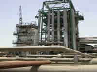
The crucial concern of power/process plant managements, the world over, is the cost
of reliable operation of plants. Setting up of new plants is prohibitively expensive
due to stringent environmental and safety concerns, uncertainties of financial return
and extended lead times for new plants. The factors cited above have driven the
managements to undertake technical assessment of their plants and equipment to prolong
their operation. Thus operation of plants and equipment till the end of their useful,
rather than design life, is the ‘Mantra’ being adopted.
|
|
|
|
|
|
|
|
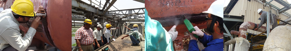
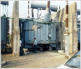
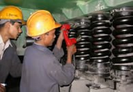
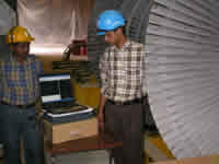
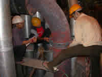
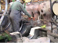
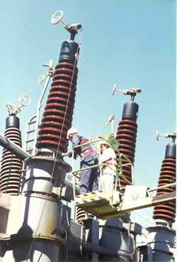
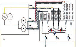
Diagnostic Testing of 200 MVA Transformer in a 400 kV Switchyard
|
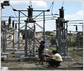
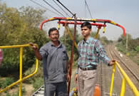
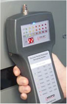
On-line Condition Monitoring of Lightning Arrester
|
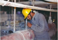
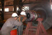
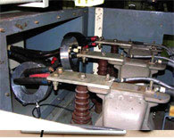
Transformer Assembly Inspection
|
|

|
Power/Process Plant and Industrial Equipment Monitored
|
|
|
The major equipment that need to be monitored on continuous basis in a power / process
plant are Generator, Turbine and its auxiliaries, Boiler and its auxiliaries, Transformers,
Switchgear, Pumps, Fans, Cables, Motors, Lightning Arresters etc.
|
|
|
Expertise, Facilities and Techniques
|
|
|
ERDA’s expertise in this important activity centers around its qualified and experienced
technical and scientific manpower and laboratory facilities such as Materials Testing,
High Voltage and Low Voltage Electrical Equipment Testing, Energy Management, Power
Electronics etc. The major techniques employed include In-situ Metallography (Replica
Test), In-situ Hardness, Fibroscopy, Boroscopy, NDT (including UT, MPT & DPT),
Steam Side Oxide Scale Measurements, Videoscopy, In-situ Chemical Analysis, Thermography,
Eddy Current Testing, Vibration –, Noise - & Sound - Intensity Analyses/ Measurements,
SPM Analysis Thermography, Partial Discharge Measurement on Transformers and CTs
by Acoustic Emission Method, C & Tan Delta Measurement using C & Tan Delta
Bridge, Partial Discharge Measurement on Rotating Machines by PD Detector, Sweep
Frequency Response Analysis (SFRA) for Transformers, Electromagnetic core imperfection
Detection (ELCID) test for interlamination, faults Insulation Failures in Motors
and Generators, Motors Current Signature Analysis (MCSA) and Motor Circuit Analysis
(MCA), Dielectric Response Analysis (DRA), Power System Modeling etc. ERDA has been
recognized by the Central Boilers Board as “Well Known Remnant Life Assessment Organization”
under Indian Boiler Act, 1950. The recognition authorizes ERDA to undertake independent
NDT & RLA of Industrial boilers, all over the country. Details of capabilities
existing at ERDA in the area of field technical services are presented in following
sections
|
|
|
Condition based Monitoring can be classified into two categories:
- On Line – Continuous Periodic
- Off Line - M/c Assembled M/c Disassembled
Online condition monitoring is possible during running condition of equipment and
it detects problems in their early stage so that rectification can be undertaken
before severe fault. Off-line monitoring requires shut down which consumes time.
It is recommended to carry out both on-line and off-line condition monitoring for
finding the exact condition of equipment.
There are various techniques for different types of equipment and their components
which can give precise information about their condition /health.
|
|
|
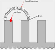
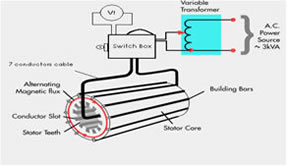
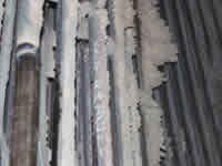
EL CID (Electromagnetic Core Imperfection Detection)
|
|
|
EL CID test is mainly for inter laminar insulation failure of Core of Motors and
Generators. It has a sensor which senses the leakage current of core (named Chattok
Coil). A current flows locally in the core caused by shorted laminations. This current
can produce dangerous local overheating or hot spots. In extreme cases sufficient
heat is generated to melt small parts of the core and can fail the adjacent winding
insulation.
|
|
|
|
|
The EL CID equipment tests a core for faults by exciting the core using a toroidal
winding to produce a ring flux up to 4% of its normal working level of excitation.
A sensing head is then passed over the surface of the core to detect magnetically
the presence of fault currents.
|
|
|
Partial Discharge Measurement
|
|
|
Partial discharge is a phenomenon of local discharges in an insulation system, it
may damage the insulation system, and it develops with respect to time.
|
|
|
PD Survey of Switchgears, Cables & Yard Equipment
|
|
|
|
PD survey is a very useful tool to detect severity level of the PD at very early
stage & in very short time. It uses inbuilt TEV & Airborne acoustic sensors
and external HFCT & Acoustic probe for detection. Following can be surveyed:
- HV switchgear equipment
- HT Cables & Termination
- HV Switchyard Equipment.
|

|
|
|
|
|
ON-LINE/OFF-LINE Partial Discharge (PD) Testing of HV Equipment
|
|
|
|
This technique involves the measurement of discharges due to voids or impurities
in insulation medium of HT machines. Discharge mainly occurs in aged machines or
machines having poor insulation system, or having unequal potential distribution
over its insulation system. This analysis gives information about condition of existing
insulation system. It uses Coupling Capacitor, HFCT (High Frequency CT), & TEV
(Transient Earth Voltage) Sensors for measurement. It uses software for bifurcating
Internal PD, Switchgear PD and Noise.
|
|
|
|
|
|
Electrical/Current Signature Analysis
|
|
|

|
This technique is applied by measuring voltages and current of the equipment and
analysing them to detect the fault within the machine. The following is indicated
by the Electrical Signature Analysis.
This technique can be applied online on AC/DC Motors & Alternators and gives
following information.
- Rotor bar & stator deterioration & severity level.
- Rotor-Stator eccentricity characteristics.
- Motor speed and slip
- Average running Current- an indicator of motor torque.
- Power factor.
- Misalignment, mechanical unbalance.
- Bearing Degradation
- Current/Voltage Variations.
|
|
|
|
Sweep Frequency Response Analysis (SFRA)
|
|
|
|
Sweep Frequency Response Analysis is a condition monitoring tool mainly to detect
the mechanical integrity of transformers. Transformers are subjected to large electromechanical
forces resulting from fault currents, which causes the core deformation and winding
movement.
During transportation and relocation, transformers are subjected to impact which
also causes winding movements. These faults if not detected will manifest into dielectric
or thermal faults within the transformer.
This technique gives information about mechanical integrity of transformers such
as winding movements, interturn short circuit, hoop buckling, axial shift, Core
damage.
|
|
|
|
|
|
Dielectric Response Analysis
|
Dielectric response analysis is a very powerful tool for diagnosis & problems
of insulation system of machines. This technique is Combination of the Polarization
and Depolarization Current method (PDC) in time domain and Frequency Domain Spectroscopy
(FDS) in a wide frequency range. The final result is the combine result of both
in FDS form.
|
|
|
Application:
|
- Analysis of water content in oil-paper insulations of Power and Instrument transformers.
- Diagnosis of Oil Impregnated Paper, Resin Bonded Paper and Resin Impregnated Paper
HV bushings
- Diagnosis of generator and motor insulation
- Diagnosis of cable insulation
|
|
|
|
|
|
Motor Circuit Analysis
|
|
Low voltage Motor Circuit Analysis (MCA) techniques involve the collection and analysis
of resistance, impedance, inductance, phase angle, current/frequency response and
insulation to ground faults. Output voltage of the test instruments are less than
9 Vac, sinusoidal output. The resulting low level alternating magnetic fields excite
the dielectric dipoles and surrounding magnetic steel dipoles, in both the stator
and rotor. Winding defects, including developing shorts, cause changes to the dielectric
and resulting dipolar ‘spin,’ which changes the capacitance of the winding circuit
at the point of defect. The resulting change affects the phase angle and current/frequency
response in the corresponding phase, causing a difference when comparing phase,
or coil grouping, to phase. As the defect progresses, the changes to the insulation
system continue, allowing trending of the defect over time.
This technique gives information about stator, rotor winding health, and contamination
in the windings.
|
|
|
Acoustic Emission Analysis
|
|
This technique is applied by measuring the Acoustic Emission signals from bearings
and gear boxes. This is ideal for Bearing, Gears, Motors, Fans, Pumps, Alternators,
Variable Speed Machines etc. This technique gives information about mechanical degradation
inside bearings, gear boxes, misalignment etc. It measures distress and noise of
bearings. Distress is summation of the clicks, crunches, whistles and groans which
are generated by defective rotating machinery.
|

|
|
|
|
Insitu Vibration Analysis
|
|
This technique is involves measurement of vibration signals of Rotating machinery
on both driving and non driving end.
Excessive vibrations in operating electrical, mechanical & chemical process
equipment in general and rotating machinery such as motors, pumps, flows, mills,
fans etc., in particular, indicate potential equipment faults. In rotating machinery.
These faults may include rotor unbalance, defects in bearings (ball roller, inner
& outer races, cage faults, etc.), crack / bent shaft, eccentricity, misalignment,
phase faults, cracked rotor bars, air gap faults, stator winding faults, shorted
laminations, variable reluctance in the magnetic circuit, etc.
Such faults can be detected using insitu vibration analysis.
|
|
|
|
|
|
Other Conventional Techniques
|
C & Tan Delta Measurement
The tan d measurement is one of the most important & powerful non destructive off
line method to monitor the condition of solid / liquid insulation of various High
Voltage equipment. Theoretically an ideal capacitive current Ic leads the voltage
in phase by 90°. A high tan d will result in thermal breakdown of the insulation
at a lower voltage. If the dielectric loss increases with the increase in voltage,
it indicates voids & PD phenomena in the insulation.
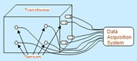
Acoustic PD of Transformers
|
This technique sense the acoustic energy dissipated from PD source inside the transformer.
It can detect the 3D location of PD source inside the Transformer by mean of distributed
sensors and calculate time of flight of acoustic signals.
|
|
Insulation Resistance & Polarization Index
IR & PI measurements are useful indicators of the presence of contamination and
moisture on the exposed insulation surfaces of a winding. They are performed to
verify the overall cleanliness, dryness, localized defects and general condition
of insulation systems.
Transformer Oil Tests
The following tests are conducted for transformer oil:
Dissolved Gas Analysis, Furan Analysis, Electric Strength (BDV), Water Content,
Inter Facial Tension at 27°C, Dielectric Dissipation Factor, (Tan delta) at 90°C,
Neutralization Value, Flash Point, Sludge and Specific Resistance (Resistivity)
at 90°C and Paper DP Test on Transformer Insulation Paper.
|
|
|
|
Experience Base
|
- Motors : Off line & On line (> 1000 jobs)
- Generators : Off line & On line (> 75 jobs)
- Power Transformers : Off line & On line (> 350 jobs)
|
|
|
Introduction |
| |
| - |
Providing root-cause analysis services for more than three decades to power plants, Utilities, SEBs, Public Sector Utilities, Private Power Utilities, Captive Power Plants and OEMs |
| - |
Helps to know the cause of failure as well as determination of remedial measures to avoid similar failures in future. |
| - |
Helps to improve upon the systems / equipment / components for better performance in all respect. |
|
|
|
Major Root Cause Analysis Studies Conducted: |
| - |
Suction casing shroud of the cooling water pump |
| - |
Turbine bearing and coupling |
| - |
Steam turbine rotor blade |
| - |
Wagon tippler shaft of thermal power plant |
| - |
Tension Clamp of 400 kV transmission line |
| - |
Hollow water cooled copper conductor of stator winding of a generator |
| - |
Bolt of condenser cooling water pump |
| - |
Rotor of an alternator |
| - |
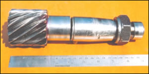
Shaft of a motor for Air-Preheater of thermal power plant |
| - |
Governor shaft of turbo-generator |
| - |
Elbow of main steam pipe line of boiler |
| - |
Piston of a 2 MVA DG-Set |
| - |
Pipe & pipe fittings of feed water line of thermal power plant |
| - |
Expansion bellows of lignite pulverizing pipe line |
| - |
Condenser tubes of thermal power plant |
| - |
Vertical shaft of bowl-mill of coal mill |
| - |
Boiler tubes – Super-heater, Reheater, Economizer, Water-wall tubes etc. |
| - |
Hydro-turbine runner blade |
| - |
Connecting Rod of DG-Set |
| - |
Transfer line of a fertilizer plant |
| - |
Discharge cooler tubes for compressor of Ammonia plant |
| - |
Gland housing & Hastelloy tubes of fertilizer plant |
| - |
Transmission shaft of drilling Rig |
| - |
Stainless steel shell of reactor of process industry |
| - |
Gear of Planetary Gear Box of a process industry |
| - |
Evaporator tube of chemical process plant |
| - |
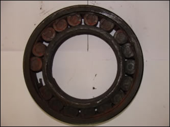
Bearing of a product discharged pump of chemical process plant |
| - |
Heat-exchanger tube of Urea plant & Ammonia plant |
| - |
Shafts of booster pump of boiler feed water |
| - |
Ball pins and metal cap of disc insulator |
| - |
Copper contact wire used on 25 kV OHE |
| - |
Brass spring guide in heavy current breaker |
| - |
Screw of plastic processing extruder |
| - |
Traction motor shaft |
| - |
Tungsten carbide tip of a cutting tool |
| - |
Feed screw of plastic processing machine |
| - |
Rusted steel plates of transformer radiator |
| - |
Tinned copper conductor of a cable |
| - |
Radiant coil of process gas heater |
| - |
Rack Pinion (Gear) of a mining equipment |
| - |
Current Transformer |
| - |
Motor Bearing |
| - |
Distribution Transformer |
| - |
Overhead Conductor |
|
| |
|
|
Boiler tube failure due to creep |
Air-heater shaft due to fatigue |
|
|
Bearing |
Overhead Conductor |
|
|
Current Transformer |
Distribution Transformer |
| |
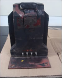
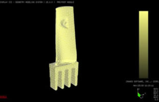
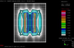
Images of Finite Element Analysis (FEA) for root-cause analysis |
|
|
Turbine Blade – Meshed model |
Piping analysis for stress distribution |
|
|
Air-Compressor Blade of Gas Turbine showing stress state
|
Transformer Core - Finite Element Analysis showing Electric and Magetic fields |
|
|
Material Evaluation Facilities available for Root Cause Analysis: |
S. No. |
Name of Equipment |
Use & Capability of Equipment |
| 1 |
Optical microscopes - Portable |
In-situ metallography |
| 2 |
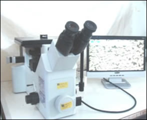
Optical microscopes – Lab. model |
Metallography |
| 3 |
Stereo-zoom microscope |
Fractography at Low magnification |
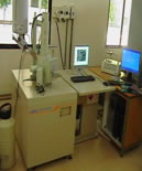
| 4 |
Scanning Electron Microscope |
Fractography at High magnification |
| 5 |
EDS Analysis (Attachment with SEM) |
Elemental Analysis of fracture surface |
| 6 |
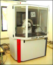
X-Ray Diffractometer |
Identification of chemical compounds |
| 7 |
Optical Emission Spectrometer (OES) |
Chemical composition analysis |
| 8 |
Ultra-Violet Spectrophotometer (UVS) |
Analysis of trace elements |
| 9 |
Universal Testing Machines – Up to 40 T |
Mechanical testing |
| 10 |
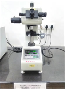
Micro hardness testing machine |
Load applied – 1 g to 1000 g |
| 11 |
Ultrasonic flaw detector |
Ultrasonic testing of metals and alloys |
| 12 |
Ultrasonic Thickness meter |
Thickness measurement |
| 13 |
Magnetic Particle Tester |
Surface flaw detection |
| 14 |
Portable Hardness Tester |
In-situ Hardness measurement |
| 15 |
Fibre scope |
Visual Inspection of Internal Surfaces |
| 16 |
Boroscope with TFT LCD Monitor |
Visual Inspection of Internal Surfaces |
| 17 |
Eddy-current tester |
Crack detection |
|
|
|
|
Optical Microscope for Metallography |
Stereo Microscope for Fractography |
|
|
Scanning Electron Microscope |
X-ray Diffractometer |
|
|
Universal Testing Machine |
Universal Testing Machines |
|
| |
|
|
1. Major Mechanical Tests for Condition Monitoring & Residual Life Assessment of
Equipment & Machinery in Power & Process Plants
|
|
|
The major mechanical tests for condition monitoring & residual life assessment
of equipment and machinery in power & process plants are as below:
|
|
|
- Visual Inspection (VI)
- Dimensional Measurement (DIM)
- Dye Penetrant Testing (DPT)
- Magnetic Particle Inspection (MPI)
- Ultrasonic Flaw Detection (UT-F)
- Ultrasonic Thickness Measurement (UT-T)
- Ultrasonic Hydrogen Embitterment (UT-H)
- Radiography (RT)
- Eddy Current Testing (ECT)
- In-Situ Metallography (RPL)
- Hardness Measurement (HT)
- Remote Visual Inspection by Fibroscopy,Boroscopy and Videoscopy (RVI-F)/(RVI-B)/(RVI-VS)
- In-situ Chemical Analysis (CA)
- Natural Frequency Test for Turbine Blades (NFT)
- Noise & Sound Analysis (NSA)*
- The rmography*
*Tests conducted on operational plant equipment only
Brief description of some of these tests is presented below:
|
|
|
|
|
|
|
Visual Examination (VE)
Visual examination is the simples and one of the most powerful techniques for assessing
the condition of plant equipment. All components are visually examined before and
after cleaning the surface by using aids such as illuminated magnifying glass, mirror,
and if needed by portable optical microscope for detecting abnormalities such as
misalignment, bow, sagging, ovality, deformation, breakage, cracking, porosity,
abrasion, erosion, pitting, etc..
Dimensional Measurements (DIM)
Dimensional measurements are essentially used to quantity changes in the present
geometrical configuration of a component with its original reference design dimensions.
As an example, outside diameter measurements are generally employed to determine
swelling (bulging) due to creep. Thickness measurements, at critical locations,
such as bends give accurate indication of thickness loss due to erosion and corrosion.
For dimensional measurements, the surface is first thoroughly cleaned by removing
scale and corrosion products using appropriate tools such as wire brush, hand grinder,
cotton cloth, etc. Subsequently, outside diameter measurements are made using digital
vernier calipers, measure tapes, bow gauges, etc; while for thickness measurements,
ultrasonic thickness meters are required.
Dye-Penetrant Examination (DPT)
Dye-penetrant examination using coloured dye is used for detection of surface cracks/
porosity / discontinuities. The components subjected to high stress and temperature
are examined after thorough cleaning, by the dye-penetrant test. Extreme care is
taken during surface preparation to avoid pre-mature closing of surface defects.
Magnetic Particles Inspection (MPI)
Magnetic particle inspection using wet fluorescent dye is employed for detection
of surface and sub-surface defects. The examination is conducted using the continuous
method i.e. the magnetizing field remains on while fluorescent iron powder particles
are sprayed. The sprayed areas are examined visually and under ultra-violet light
of appropriate intensity. Magnetization is done in at least two perpendicular directions
to ensure high probability of crack detection. All relevant indications are recorded
by identifying their location, nature, and size on a sketch and/or by a colored
photograph.
All weld joints are examined by MPI to check for presence of surface and sub-surface
defects. On completion of a given test, residual magnetism remaining in the component
is removed by de-magnetization.
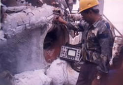
Ultra-Sonic Shear Wave Examination (UT-S)
Ultrasonic Examination method is employed for detection of surface cracks, loose
bonding, volume cracking and any other kind of defect to ensure internal soundness
of the component. The examination is usually carried out on header butt joints,
drum-weld joints, as well as on other joints deemed critical.
The ultrasonic test equipment is properly calibrated prior to use. The resolution
& sensitivity level of the equipment is set to record the presence of the smallest
possible defect size. It is to be noted that a typical advanced ultrasonic instrument
(of the kind used by ERDA) has adequate sensitivity to detect even fine multi-branched
cracks resulting as a consequence of stress corrosion cracking.
In-Situ Metallographic Replication (RPL)
Metallographic examination by portable optical microscope and by surface replication
technique is carried out to assess the micro-structural state of the plant component.
The replication technique is used at selected locations on the components to reproduce
accurately metallographic features such as distribution, size, and morphology of
the carbide precipitates as well as micro-cracks typical in case of stress corrosion
and Hydrogen embrittlement.
The locations selected for examination are properly polished with a portable grinder
and etched with suitable chemicals for examination under a portable microscope.
The reverse image replicas of the metal surface are taken on a plastic replicating
film for detailed laboratory examination under an optical microscope. The quality
of the replicas is checked at site by a portable optical microscope before bringing
these to the laboratory, for further analysis.
Hardness Measurement (HB)
In-situ hardness testing is carried out on all components operating at high stress
to determine the extent of micro-structural degradation. The locations for hardness
measurements are selected based on results of various other tests including visual
examination. The measurements are taken using a Portable Hardness Tester. Before
using this device, its accuracy and reproducibility is checked using pre-calibrated
standard test blocks.
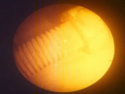
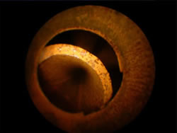
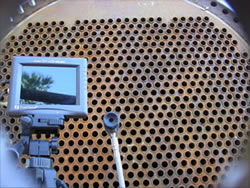
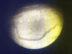
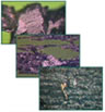
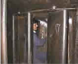
Remote Visual Inspection (RVI)
Fibroscopy / Boroscopy / Videoscopy are optical visual examination techniques used
for examining & recording visual/video images of internal condition of various
components of boiler, turbine & auxiliaries such as headers, tubing, piping,
rotor bores, etc., for determining the presence of internal defects such as internal
cracks, corrosion and erosion, oxidation, deposits, pitting, blockages, choking,
as well as presence of foreign objects such as left over welding consumables, steel
pieces, cuttings, spattering, welding slag, refractory and insulating materials,
etc. Fibroscopy, boroscopy, and videoscopy is carried out up to a length of eight
meter inside each accessible component. Fig. 3 shows typical images obtained from
fibroscopic and boroscopic examination of headers and heat exchangers. The image
can be recorded using freeze frame digital photography or a continuous video record
can be made.
Eddy Current Testing (ECT)
The eddy current flaw detection technique is based on the principle that a time
varying magnetic field induces a circulating current in the near surface regions
of metallic/conducting material, when a probe in the form of a coil carrying a time
varying current is brought near a conducting surface to be examined. The mutual
inductance of the scanning coil - surface being examined changes in the presence
of surface and sub-surface flaws. This translates into a change in the scanning
coil impedance, based on which the presence of flaws can be detected.
In-Situ Chemical Analysis (CA)
Insitu chemical analysis is usually conducted on turbine components. However, insitu
chemical analysis is also widely used for identifying & verifying pressure part
chemistries in steam generators using advanced materials. Before the analysis, a
wire brush and grinder are used to thoroughly clean the surface. A portable state
of art instrument operating on the principle of spark emission /XRF spectroscopy
is used for conducting this analysis.
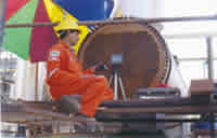
Natural Frequency Test (NFT)
The vibration energy associated with an engineering structure undergoing dynamical
excitation under time varying externally applied forces is primarily concentrated
at the characteristic frequencies (eigen-values) of the structure. Since concentration
of excessive vibration energy can lead to excessive vibrational amplitudes with
accompanying large time varying stresses, the vibrating structure becomes prone
to failure by the process of fatigue. In a turbine, the components most prone to
failure by this mechanism are the rotor blades. Among the various turbine stages,
the blading associated with the low pressure stages - especially the last couple
of stages – are the most prone to excessive vibrations excited by the various disturbing
forces encountered in a turbine. It is thus important that the fundamental vibration
frequencies of the low-pressure blading be accurately determined using a suitable
technique.
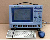
The technique used to determine the natural frequencies of blading involves exciting
of blade packets by hammering (to simulate an impulse load) with an instrumented
tuned hammer and the resulting vibrations, as picked up by an accelerometer, are
recorded using a digital storage oscilloscope and subsequently converted into a
frequency domain transfer function record of the original signal using a Fast Fourier
Transform (FFT) algorithm. The natural frequencies of the first three vibrational
modes are subsequently extracted from this transfer function record.
|
|
|

Viewing Directions of angle of view on the image obtained by fibroscopic / boroscopic
examination
|
|
|
|
|
|
|
Bolt lying inside header
|
Oxide scale inside main steam pipe
|
|
|
|
|
General view of heat exchanger
|
Broken tube found in heat exchanger
|
|
|
|
Fibroscopic & Boroscopic Images of Headers and Heat Exchangers
|
|
|
|
|
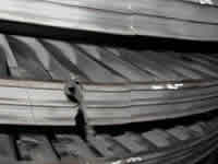
|
In-situ Oxide Scale Measurement
In-situ oxide scale measurement is extensively used for determining residual life
of high-pressure, elevated temperature, components. For measurement of oxide scale
thickness in a high temperature tube, a portable ultrasonic flaw detector with special
high resolution, high frequency, small diameter probes are used.
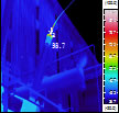
Thermography
Thermal imaging is a non-contact type technology that makes use of the infrared
spectral band to determine the surface temperature from a safe distance. These images
make it quick & easy to check surface temperature and identify hot-spots. These
hot-spots (or rise in temperature) often indicate impending failure which can be
averted using thermography. Using thermal imaging, unplanned production downtime
can be minimized, resulting in better productivity. Thermographic survey is a fast
and cost-effective on-line technique which causes no disruption in the running of
the plant. Faulty fuses, weak insulations, loose connections and bad joints, obstructed
cooling and overloaded circuits are sometimes not visible to the human eye and are
often overlooked during routine visual inspection. Without the use of thermography,
many of these problems go unnoticed until disaster strikes.
Noise Level Measurement
The harmful effect of excessive noise is well recognized. The amount of noise depends
on the type of machine installed, its operational mode and also the way power is
applied & transmitted. This test determines sound power lever or sound pressure
level for airborne noise emitted by rotating or static electrical machines such
as transformers, induction motors, process reactors etc.
Based on measurement of sound power and sound pressure and comparing with reference
measurements, indications of potential equipment problem can be identified and pin-pointed.
|
|
|
2. RLA and Condition Assessment Services offered by ERDA
NDT Services
|
|
|
- Visual Examination
- Dimensional Measurement
- Liquid Penetrant Testing
- Magnetic Particle Inspection –Yoke
- Magnetic Particle Inspection –Coil
- Magnetic Particle Inspection –Prod
- Magnetic Field Measurement
|
- Ultrasonic Normal Wave for Flaw Detection
- Ultrasonic Thickness Measurement
- Ultrasonic Hydrogen Embrittlement
- Ultrasonic Shear Wave for Flaw Detection
- Radiographic Inspection
- Eddy Current Testing
- In-Situ Metallography
|
- In-Situ Hardness Measurement
- In-Situ Hardness Measurement
- In-Situ Oxide Scale Measurement
- Remote Visual Inspection By Fibroscopy
- Remote Visual Inspection By Boroscopy
- Remote Visual Inspection By Videoscopy
- Natural Frequency Test
|
|
|
|
|
|
|
Mechanical Condition Monitoring
|
|
|
- Thermography
- Acoustic Emission Analysis (AE)
- Vibration Measurement and Analysis
- Noise / Sound Measurement
- Shock Pulse Measurement (SPM)
- Ferrography Analysis
|
|
|
|
|
|
|
|
|
|
|
Typical thermograph
|
Noise meter
|
Vibration analyser
|
Ferrograph
|
Wear particle analysis
|
|
|
|
Laboratory Testing (included in RLA Scope) Services
|
|
|
- Dimensional Measurement
- Tensile Testing Including UTS,YS & % Elongation
- Microstructure Examination
- Hardness Measurement
- Chemical Analysis
- Flattening Test
- Flaring Test
- Hydrogen Embrittlement
- Weight Loss Analysis
- Deposit Analysis
- SEM (Scanning Electron Microscopy)
- EDAX (Energy Dispersive X-Ray Analysis)
- XRD (X-Ray Diffraction)
|
|
|
|
|
Tensile Testing Machine
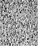
|
Microstructure of Low Alloy Steel
|
X-ray Diffractometer
|
|
|
|
|
|
|
|
|
|
|
|
|
|
| |
|
|
|
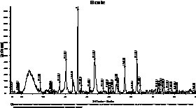
|
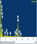
XRD image |
EDS Spectrum of Deposit |
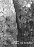
SEM Image |
SEM with Electron Dispersive Spectrometer |
|
| |
NDT & RLA Services for Hydro Power Plant Components |
| |
HYDRO TURBINE |
| |
- Turbine Shaft
- Shaft Coupling Bolts
- Runner Blade
- Guide Vanes
- Thrust Bearing Pads
- Lower Guide Bearing Pads
- Penstock Gate Shaft
|
 |
| |
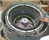
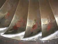
Condition of Francis runner |
|
| |
HYDRO GENERATOR |
| |
- Stator Winding
- Rotor Field Winding
- Core
|
|
|
|
NDT tests in progress in stator
of hydro generator |
Overview of stator of hydro generator |
Inspection of guide vanes |
|
| |
NDT/ RLA Services For Steam Turbines |
| |
HP/IP/LP TURBINES |
| |
- Casing
- Glands
- Diaphragm & Stationary Blades
- Nozzle Box
- Steam Admission / Balancing Pipe
- Cross Over Pipe & Bellows of LPT Assembly
- Parting Plane Studs
|
|
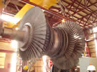
|
Turbine Rotor |
Close-up of damaged diaphragm |
|
|
Boroscopy of Heat Exchanger |
Open Turbine |
|
|
Eddy current test |
Overview of steam piping |
|
|
Dimensional Measurement |
NDT testing on parting plane |
|
| HP/IP/LP ROTORS |
- Journal & Shaft Surface
- Blades
- Fir-Tree Blade Grooves of LP Rotor
- Coupling Bolts
|
| BEARING & OTHER SYSTEMS |
- LP/ HP/ IP Bearings
- Thrust Bearings
- Barring/Turning Gear
|
| STOP VALVE & CONTROL VALVES |
- HP / IP / LP / By Pass
- By Pass Water Injection Control Valve
|
| STEAM PIPING |
- Main Steam Piping
- Hot Reheat Piping
- Cold Reheat Piping
|
| CONDENSER |
- Condenser Tubes
- Supports & Baffles
- Cold Reheat Piping
|
| |
| |
|
NDT & RLA Services for Boiler Components
(Approved by Central
Boiler Board as well known Remnant Life Assessment Organization, under Indian Boiler
Act 1950) |
| ECONOMIZER SYSTEM |
|
|
|
|
|
|
|
|
|
|
| |
|
|
A collage of photographic records of visual inspection of steam generator |
|
- Feed Water Piping
- Economizer Headers
- Economizer Coils
|
| CIRCULATION SYSTEM |
- Boiler Drum
- Down Comers
- Water Wall Headers
- Furnace Water Wall Panels
|
| SUPER HEATER SYSTEM |
- Super Heater Headers
- Platen SH Headers
- Final SH Headers
- LTSH Coils
- Platen SH Panels
- Final SH Coils
- Attemperator & Link Pipe
- PRDS
|
| REHEATER SYSTEM |
- Cold Reheat Headers
- Hot Reheat Headers
- Reheater SH Coils
|
| PIPING SYSTEM |
- Main Steam Piping
- Cold Reheat Piping
- Hot Reheat Piping
|
| Support Structure & Ceiling Girders |
|
|
|
|
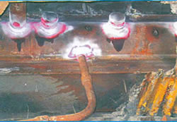
Magnetic Particle Test on Support Springs of Condenser Unit of Power Plant |
Broscopy of Turbine Rotor Shaft |
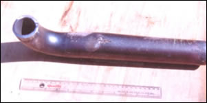
Main Steam Pipe Failure of Process Plant |
|
|
The Energy Management Section (EMS) of ERDA was established in the year 1995 with
the objective of providing energy conservation services to the Nation. The energy
audit studies undertaken by the EMS have covered Industries, Power Generation Utilities
(GENCOs), Power Distribution Utilities (DISCOMs), Commercial Complexes, Hospitals,
Dairies, Municipal Corporations, etc. EMS has carried out more than 250 energy audits
until now and the benefits realized by our esteemed clients by implementing our
recommendations are quite handsome. Over the years, EMS has specialized in energy
conservation related to conventional fuels such as coal, oil & gas. These conventional
fuels are limited and will be exhausted shortly and thus the need arises to reduce
their consumption by efficient utilization. The supply and demand gap of electric
power is increasing every year and is expected to increase even further due to the
huge cost required in setting up of Thermal Power Stations as well as the associated
environmental pollution.
Energy conservation is an optimal operational practice, which improves the efficiency
of the equipment associated with both supply side and demand side i.e. at the user
end. Since the industries account for a greater share of power consumption, energy
conservation programs will benefit them by reducing their Specific Power Consumption
and making them more competitive in the market. ‘Negawatt’ (a negative ‘Megawatt’),
a term coined by the renowned energy analyst Amory Lovins, highlights the fact that
a Negawatt produced by reducing energy need saves more than a Megawatt generated.
Energy audits lead to the generation of “NEGAWATTS” and thus result in virtual augmentations
to the installed power generation capacity of the Nation! |
|
|
CONDENSER
Energy Audit is the basic tool of energy conservation and is defined as a systematic
exercise to identify the end-uses that consume significant amount of energy, estimate
the efficiency in each of these end uses and devise methods for improving efficiency
and thus curbing losses and wasting energy.
A walk-through audit at the client’s place is undertaken to study the manufacturing
process, the type of equipment available, their operating strategy and potential
areas of energy conservation. The detailed list of equipment is collected along
with the electricity bill for the two previous months for working out a detailed
quotation for the energy audit to be conducted at the client’s premises.
EMS is having all sophisticated portable non-invasive instruments and highly skilled
& experienced staff for conducting measurements at site. The energy audit report
is prepared on the basis of these measurements and includes the saving potential,
investment required and the payback period for investments made. Due emphasis is
also given to “No Cost” measures that include good housekeeping practices, minor
changes in the operation practices, etc. No cost saving potential of 11% to 100%
was realized during the course of energy audit programs in addition to other energy
conservation measures with payback period ranging from few days to 2 years
Core Areas of Activity
- Energy audit study
- Energy conservation measures
- Seminars, workshops and in-house training programs on energy audit
- Certification of energy efficient equipment
- Research and development in the area of renewable energy
Core Areas of Activity
- More than 250 comprehensive energy audits have been successfully completed.
- The list of auditees includes Navaratna companies such as ONGC, GAIL, NTPC, etc.
- Other prestigious clients include IPCL, ESSAR Steel, General Motors, KRIBHCO, Heavy
Water Plants of DAE, GNFC, GSFC, etc.
- Successfully completed the energy audit for both process and equipment at Tata Steel,
Jamshedpur, and Jindal Steel & Power, Raigard
- Power Generating Units of utilities such as National Thermal Power Corporation (NTPC),
Nuclear Power Corporation of India Ltd., (NPCIL), Gujarat State Electricity Corporation
Ltd., (GSECL) Maharashtra State Power Generation Co. Ltd., M.P. Power Generating
Co. Ltd., Torrent Power etc.
- Unique distinction of having completed energy audit of 129 Generating Units of 59
Power Plants Including 77 Coal based Thermal Units, 3 Lignite based Units, 13 Gas
based Units, 27 Hydro Units, & 9 Nuclear Generating Stations. Saving potential of
up to 64% and 43% were identified for electrical and thermal energy, respectively.
- Annual recurring savings to the tune of Rs. 163 crores have been reported as achieved
by the audited industries and utilities.
- The identified saving potential is equivalent to 49 MW per year
Major Recognitions
EMS, ERDA is recognized as authorized energy auditor by Bureau of Energy Efficiency
(BEE), New Delhi (under Energy Conservation Act-2001), Petroleum Conservation Research
Association (PCRA), Gujarat Energy Development Agency (GEDA), Maharashtra Energy
Development Agency (MEDA), Energy Management Centre (EMC)-Kerala, Chhattisgarh State
Renewable Energy Development Agency (CREDA), Commissioner of Electricity, Gujarat
for Statutory Energy Audits in Gujarat State.
Honors & Awards received by Energy Audit Group
- Best Improvement in Performance Award from PCRA consecutively for 3 years.
- Best Energy Auditor Award from PCRA consecutively for 2 years.
- MEDA Award for the years 2004 & 2005
|
Power system operations have already become complex due to many factors. Expansion
and interconnection of individual systems to improve reliability has added this
complexity. The operation of a network economically without jeopardising the security
is the FOCUS of system operating engineers. Availability of a large number of computer
softwares can assist power engineers in handling the complexities of the power systems.
ERDA’s Enhanced Capabilities in Power System Studies
ERDA has capabilities for solving Power System problems by utilizing Sophisticated
Computer Software in the areas of Load Flow, Short Circuit, Relay Coordination,
Transient Stability, Dynamic Stability, Voltage Instability, Power Evacuation Studies,
Islanding Strategy, Failure analysis study, Harmonic Content Analysis etc. ERDA
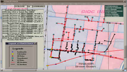
has MI-POWER and in-house developed POWERTRACK software for this purpose.
Inspection Services for RGGVY, HVDS, Feeder Separation Works
ERDA is engaged by many utilities for carrying out independent quality checks. ERDA
regularly deputes large teams of skilled engineers to visit site to carry out third
party inspection, supervision and monitoring as per the REC norms. ERDA also conducts
field studies which include, consumer indexing, asset codification using GPS instruments,
designing of HVDS systems, preparation of BOM/BOQ for feeders as so on.
Energy Audit / Consultancy Services
ERDA undertakes Energy Audit projects in full and part for distribution systems
to investigate the losses in the distribution system (both technical and commercial)
so as to identify the loss pockets. ERDA also gives system improvement suggestions
through feeder reconfiguration, feeder bifurcation, reconductoring the network etc
with payback period.
ERDA is one of the consultants for a massive programme of up gradation of Sub-Transmission
and Distribution system and reduction of Aggregate Technical & Commercial losses
launched by the Govt. of India under the Restructured Accelerated Power Development
and Reforms Program (R-APDRP).
ERDA laboratories are fully equipped with sophisticated testing instruments and
qualified and trained personnel to provide a wide range of testing and Evaluation
Services as per National, International, Institutional and Client specifications.
These services are available for developmental -, type - and certification - testing
of materials and products.
- 50 kA & 120 kA On-line Short Circuit Test Laboratories for Switchgear and Distribution
Transformers
- High Voltage Impulse Testing Facility
- 40 ton IP (Ingress Protection) testing
- EMI/EMC Testing
- LOCA (Loss of Coolant Accident) Qualification Testing
- Seismic, Vibration & Shock Testing
- RIV corona measurement upto 600 kV
- Calibration of EHV Measuring System at Site
Materials / Products
Insulating Materials, Conducting & Contact Materials, Magnetic Materials, Structural
Materials, Composites, Ceramics, Coatings, Elastomers, Polymeric Materials and T&D
Hardware. Electrical Products like HT/LT Capacitors, LT/HT Cables, Domestic Electrical
Appliances and Wiring Installation, Lamps & Luminaires, Rotating Electrical Machines,
Pumps, Switchgear and Controlgear Products, Transformers, CTs, PTs, Reactors, Energy
Meters, Diesel Engines, etc.
Our Clients
ERDA is providing these services to State Electricity Boards and other Utilities
including MGVCL, DVVNL, MVVNL, MPMKVVCL, MPPKVVCL, DHBVN, MESCOM, BESCOM, APCPDCL
etc. Regulatory Agencies including GERC, CSERC, MPERC, Private and Public Sectors
including NTPC, PGCIL, IOCL, GAIL, GNFC, GSECL, GETCO, ABB, Areva, Alstom, EMCO,
Voltamp, Crompton Greaves, Siemens, L&T, Reliance, Bharat Bijlee, Kirloskar, GSFC,
GIPCL, NPCIL (RAPS, TAPS MAPS, NAPS & KAPS), SKF, FAG, HINDALCO, ISPAT Industries,
Essar Steel, Essar Power, ULTRATECH Cement, various OEMs etc.
|
| |
|
|
|
|